Deleted
Deleted Member
Posts: 0
|
Post by Deleted on Apr 24, 2008 17:02:26 GMT -7
Since an automobile engine is basically an air pump and how fast or efficiently you move the air through it determines how fast you go then it stands to reason that a t-jet is an electric pump. You need to make sure that the electrical connections are optimum and that the electricity flows unrestricted through to the motor. How many electrical connections are on a t-jet chassis? 1. Pickup shoe to track rail 2. Pickup shoe to hanger plate 3. Hanger plate to bottom hanger plate (notice the rivet that holds them together?) 4. Hanger plate brush spring to motor brush 5. motor brush to motor comm plate Your job is to make sure there is little or no arcing across those connections. How to do it? I dunno - I've been trying to figure out all those connections ever since I've been racing these things. Notice the pickup shoe on the right is properly adjusted since the whole shoe is contacting the track rail. Now notice the left rail needs some adjusting as the rear portion isn't in contact with the track rail. Speed is being lost because of this improper adjustment.  I made a tool from a tiny screwdriver and using a steady hand and the Dremel diamond wheel I cut a slot into it.  Notice where you grab the pickup shoe to adjust the angle - twist the shoe to bend it ever so slightly then run it again and see what the results are. This takes time so be patient. You can also set the car on a piece of test track (small piece you cut of of some old track) and look from the sides to see if the pickup shoe pad is resting flat on the track rail.  |
|
Deleted
Deleted Member
Posts: 0
|
Post by Deleted on Apr 24, 2008 17:05:22 GMT -7
What about your hubs - if you are using stock hubs I can probably guarantee that they will be out of round. Here is an AFX hub on an axle inserted into the Dremel. I hold it very steady and slowly take little bits of the wheel down by grinding it against the metal file.  I stopped to show that the hub was in fact out of round as you can see the paint missing on one half as I'm truing up the hub.  |
|
|
|
Post by johnbalich on Apr 24, 2008 17:18:06 GMT -7
excellent stuff!
|
|
Deleted
Deleted Member
Posts: 0
|
Post by Deleted on Apr 24, 2008 22:18:10 GMT -7
Ok last of the tips - I've got to save a couple of them for myself. I'm probably taking this a little far but if reduction of friction is the overall goal then what about these tips. I bevel the bottom edge of the top clip so that if the idler gear bounces up while the motor is running then the teeth don't run into a sharp edge but rather a beveled edge that doesn't cause as much friction on the gear.  What about the comm plates - I take an Xacto blade and draw it across the leading edge of the comm plate that first comes in contact with the motor brush. If the brush has a nice ramp to ride up onto and not a sharp edge then it will most likely make a smooth transition to the next copper plate. Otherwise I'd imagine that it would bounce the brush when it hits the leading edge if it isn't beveled resulting in less time that the electrical connection is being made.  |
|
Deleted
Deleted Member
Posts: 0
|
Post by Deleted on Apr 24, 2008 22:21:39 GMT -7
Make sure to clean the crud out from between the comm plates - after all the dust that comes off the motor brushes conducts so if enough of that dust got in between the comm plates theory would seem that it could short between the copper comm plates.  |
|
Deleted
Deleted Member
Posts: 0
|
Post by Deleted on Apr 24, 2008 22:33:20 GMT -7
You might notice the fact that there is some mounting slop on the rear shaft when it comes where the gear is located. Notice there is a gap between between the 9 tooth gear and the bottom side of the top plate. I'd drive one of the two gears (top gear or the 9 tooth gear) towards the other one to remove some of that excessive gap. Be careful and don't drive it too far and bind up the gear against the top plate.  Lastly - remove the motor magnets and motor brushes. Re-assemble the t-jet without those two components and then spin the rear tires to see how smooth your drivetrain is. It should spin freely - try this in both directions. If not then you've got some work to still do. |
|
Deleted
Deleted Member
Posts: 0
|
Post by Deleted on Apr 24, 2008 23:31:55 GMT -7
Where to get the tools to work on t-jets? ( I remember back in the day that a screwdriver, needle nose pliers and a tiny hammer were all that we had.) I use a lot of stuff from Rick Terry. www.rt-ho.com/tools.htmlThere are many other tool makers as well - the race sponsors carry lots of their stuff too. |
|
|
|
Post by johnbalich on Apr 24, 2008 23:51:16 GMT -7
lucky bobs also sells gear pullers and wheel and presses.
|
|
|
|
Post by kdog on Apr 25, 2008 3:27:49 GMT -7
Very nice group of articals Jet, there is some stuff I have never considered very cool !
|
|
|
|
Post by nightrider on Apr 25, 2008 18:35:56 GMT -7
Jet!
Great tutorial!! Glad to have you in the group,please keep this type of info coming!! I even learned a few things.. Great JOB
Chris
|
|
|
|
Post by SKR on Apr 28, 2008 17:58:16 GMT -7
As Jet talks about above. Here is a way to get a closer look at how your pick up shoes ride. Tweak them to run as flat as possible. Jet demonstrates a great tool he made above in his post. Old piece of Aurora track. Let's chop this mother up!  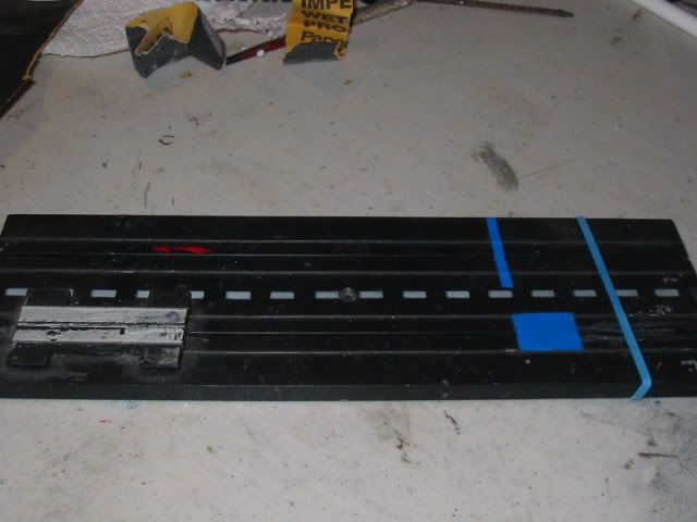 Take a Dremel with a cut off tool and cut along the rail. 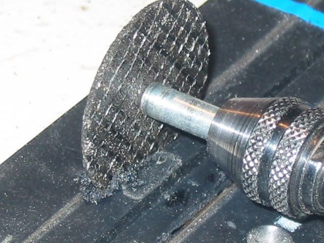 Use a round grinding stone on your dremel to smooth things up after your rough cut with the cut off wheel. Here is what my test track looks like after completing. 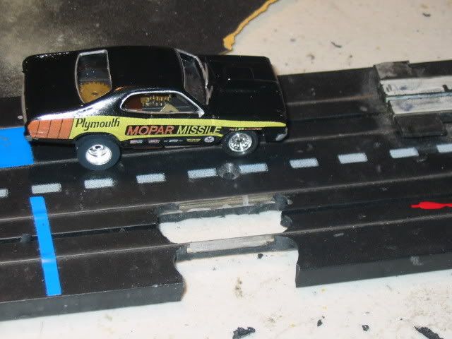 A view from below. You can see the front of the shoe is up a little 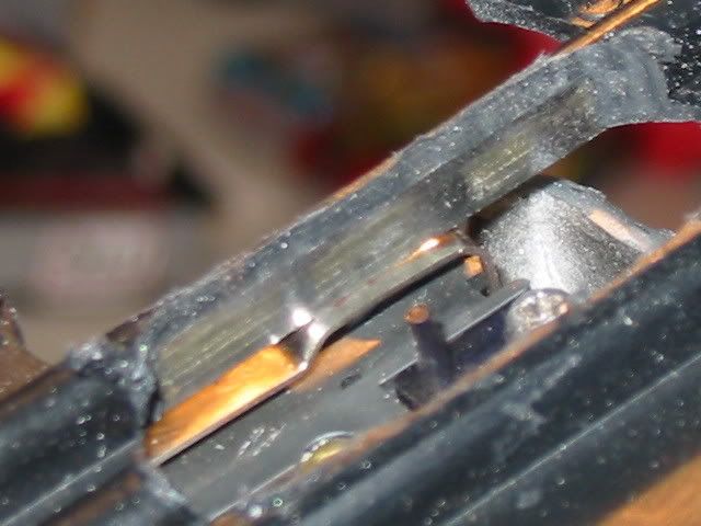 From the side 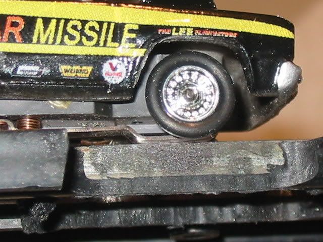 |
|
Deleted
Deleted Member
Posts: 0
|
Post by Deleted on May 16, 2008 8:04:29 GMT -7
How are racers attaching extra weight to the chassis for the Super Stock race? Super Glue does not seem to be doing the trick.
Any chance we could modify the Super Stock rules to allow the weight to be attached to the underside of the body as long as it is not visible?
|
|
|
|
Post by SKR on May 16, 2008 9:43:26 GMT -7
I'm all for being able to attach weight to the body also as long as it's not visible. I use Shoo Goo to attach the weight. Hobby Lobby sells E Goo which seems to be the same stuff also.
John, is this OK with you? If so, could you update the rules? Thanks!
|
|
|
|
Post by johnbalich on May 16, 2008 14:16:12 GMT -7
perfectly acceptable................Ill post it today
|
|
|
|
Post by SKR on May 31, 2008 6:48:15 GMT -7
I've found this to work better at least here on our track. This will drop the frond end .018 putting more pressure on the pick up shoes. 5.32" I.D. (9/32" O.D.) by 1/16" width O-Rings. I found theses at Lowes for 59 cents. 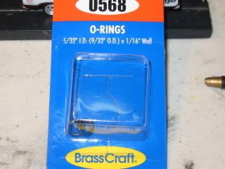 RRR stock front tires. .384" 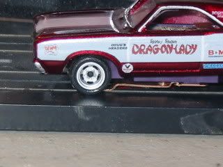 To help mount the orings I rolled the orings from the ball tip side up onto the pen body. 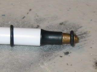 After the orings are both in place I butted the pen body up to the wheels tight and rolled each one over to the front wheels. 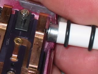 Picture from the bottom side of the chassis. 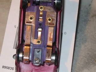 Side view, new orings mounted are .366" and they touch and roll on the track. I've also had better e/t's by taking the front tires you just took off and placed them on the rear. 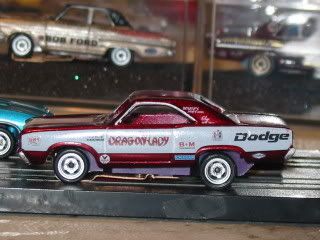 |
|